内田秀男
A METHOD OF DETECTING AURA PHENOMENA
By Hideo Uchida
As the result of prudent experiments, it was proved to exist the following phenornena.
The electrical charge is induced corresponding to only the electric field by electro-magnetic radjation energy and have no relation to the magnetic field when a conductor tip is moved in the electric field by the electro-magnetic radiation energy. ln this phenomena, it is difficult to shield electrically.lt isassulned as the Erectric Field lnduction Effect (E.F.I.E.). By a measuring equipment applied the E.F.I.E.,experiments and obsavation of aura phenomena in the life environment are tried. ln cooperation with mediums who can directly observe the aura, it was confirmed to detect and observe the facts of existing aura phenomena around such as animals, plants, minerals, all things in nature or hfe environment, heavenly bodies in the space as well as around all human bodies.
By these matters mentioned above, the riddle of nimbus from the back of Buddha or Awagihara in JapanShinto also become to be solved. And further the following unknown phenomena can also be found. That is, There are some fields similar to the electrostatic fields in the radiation fields of electro-magnetic wave energy. About these phenornena, l would like to bring forward a new problem showing many collected data of experiment.
1. まえがき
この報告は人体をはじめ、生活環境のすべてに存在するといわれているオーラ現象に関して、オーラが肉眼で直視できる霊能者多数の協力を得て、1963年以来、調査、実験、研究をなした結果、オーラ現象が電磁気学の分野の既に周知の技術を応用して、実測し得ると考えられる仮説“電場誘導効果”を得たことに関するものである。
電場誘導効果は、約130年前、英国のファラディ教授が発見した電磁誘導効果に似ているようであるが、基本的にこれとは異なるものである。
電磁誘導効果は、導体(コイル)が磁場の方向に直角に動くときに、起電力が発生する現象であるが、これに対して、電場誘導効果は物体片が放射電磁エネルギーによる電場のなかを放射方向に平行して動くとき、磁場には関係なく電場のみに対応し物体片のなかに電荷が発生する現象である。そしてこの現象は、電気的にシールドすることが困難である。
この動く物体片に導体、または半導体の一片を使うと、発生した電荷を集めても電流として検出できる。
この現象は周知の静電効果とは基本的に異っている。静電誘導は導体片が動かなくても、強い静電界ではそこに電荷が発生する。しかし、静電界は周知のように距離の二乗に反比例して分布するため、微弱名静電界では、最早固定した導体片に発生する静電誘導は検出できない。
ところが微弱な静電界でも、その分布を乱す原因があると、固定した導体片に静電界の乱れに対応した電荷が発生する現象が起こる。(参考資料-1)
これは静電界に於ける電気力線分布の変化に対応し、導体片の電荷の分布が変化し、結果的に以下に述べるオーラ現象の測定手段と考えられる電場誘導効果の基本的な現象を生じている。
一般に導体は、負の滞留電荷に満ちていると考えられる。そしてこの負の滞留電荷は、その導体の周囲の電気力線分布に対応して分布が変化すると考えられる。しかし、この導体を電気的にシールドするときには、導体周囲の電気力線分布が均一化されると考えられるので、導体をシールドした場合には、シールドの外側に起る電気力線分布の変化の影響は、シールド内の導体には及ばないと考えられている。
しかし、オーラ現象を伴う放射電磁エネルギーの電場のなかで動く導体は、導体のシールドの有無にかかわらず 導体のなかの負の滞留電荷の分布に変化を生じ、結果的に電荷、電流の発生現象を引き起すことが、慎重な実験の 返しから明らかになった。
以下に述べる報告は、種々の基本的な項目の研究結果である。
2.測定の原理と要領
この現象を検出するには、つぎに述べる方法を用いた。即ち第1図aに示すように、電場のなかで動かす導体片は、周囲の空間の電気的絶縁抵抗より、極めて大きい高抵抗を通して接地する。これにより、負の滞留電荷の変化は、抵抗を通して電流、電圧の変換をする。この電圧変化を高利得の直流増巾器で増巾して指示器で検出する。但しこの場合、導体片にシールドがないときはもちろんであるが、空間にある放送電波や、商用電源からの誘導妨害を除去する濾波器を直流増巾器の人力側に接続する。(第1図b)
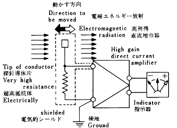 Fig.1-a Principleof measurement オーラ測定の原理 |
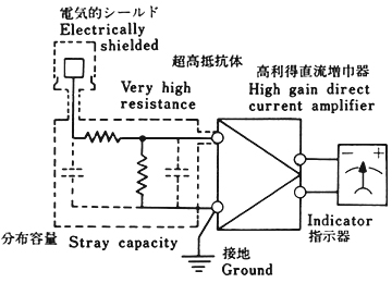 Fig.1-b Above capacity and resistance construct a filtering circuit for interference. 分布容量と超高抵抗体が、妨害信号のフイルターを構成する。 |
また、導体片をもつプローブの動く方向に対応して増減する負の滞留電荷の変化を検出するには、プローブを停止した状態でバイアス電圧を調整して、指示器のゼロ位置をセットする必要がある。このゼロ調整は、導体片の周囲の静電気や、イオン帯電による電界の影響を除去するために必要である。
以下に述べる実験結果を得るには、環境の至るところに、天体電磁波によるオーラが充満している。そして、人体はもちろん、すべての器物からオーラが放射しているので、実験測定に際してこれらの影響を除去する工夫が必要である。したがって、もしプローブを動かして測定するときは、これらの環境定数を較正する必要がある。 もし放射源を動かすときは、動かす台による静電場の乱れや動かすことによって発生する台自体からの電場誘導の影響を較正する必要がある。
これによって検出される電場の形状は、10名の霊能者の協力により、オーラ放射の形状と極めて相似していることが確められた。憤重な実験によると、瞬時に変化するオーラの状態は検出しがたいが、定常状態に於けるオーラの外観形状は検出できることがわかった。
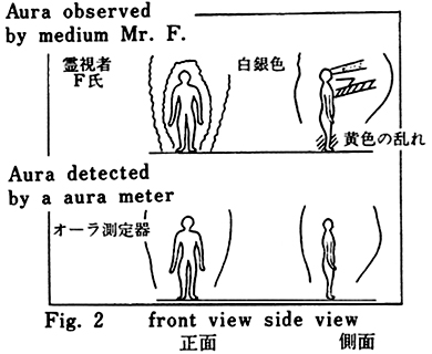
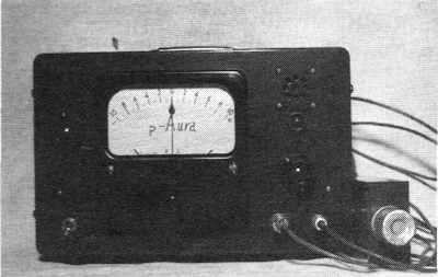
Photo-1 Aura meter
オーラメータ
写真-1は、試作したオーラメータである。
第2図は、人体オーラについて、霊能者が観測したスケッチ図と、オーラメータによる実測形状との比較例である。
この電場誘導より検出される電荷増減の変化と、放射電磁エネルギーによる電場強度との関係はつぎのようである。
A. エネルギー放射源が、一般の電磁波の場合、 a. 近づくとき、即ち放射エネルギーの揚がより強い方向に変化するときには、検出プローブの導体片に負電荷が増大し、離れるとき、即ち放射エネルギーの場がより弱い方向に変化するときには負電荷が減少する。実験によれば負電荷の増減量ΔQは、つぎのような関係がある。
ΔQ ∞ A・E・V
A:導体片の表面積
E:放射エネルギーの場の強さ
V:動く速度
放射エネルギーの場内の任意の一点に於いて、検出指示器をゼロにセットした場合、ΔQの検出極性は、Eがより強くなる場の方向では、−、即ち負電荷が増大し、Eがより弱くなる場の方向では、十、即ち負電荷が減少する。
b. プローブの導体片を、電気的にシールドした場合には、シールドによる電気的減衰を伴うが検出極性が逆転する。
B. エネルギー放射源が、火花放電による電磁波の場合
A -a と同様の検出極性であるが、シールドによる検出極性の逆転がない。
C. エネルギー放射源が、太陽、アイソトープの場合
Bと全く反対の現象を伴うが、シールドによる検出極性の逆転がない。
D. 放射エネルギーの場内に於いて、プローブを一定速度で円運動をなして検出する場合、つぎのような関係になる。
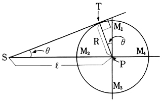 Fig.3 Diagram for detecting value |
S : Radiation source P : Center of rotation R : Rotation radius for tip of conductor l:Distance from radiation Source θ:Incident angle to tip of conductor T : Maximum detecting point Assume to rotate tip of conductor as M1→M2→M3→M4around orbit. |
S:放射源 P:測定のための回転中心 R:検出探針の回転半径 l:放射源からの距離 θ:検出探針の入射角 T:検出値最大点 図に於いて、検出探針がM1→ M2→M3→M4 と円軌道回転 すると仮定する。 |
第3図に於いて、S:放射源、P:Sによる放射エネルギーの場内の任意の一点で、測定のための回転運動の中心、 R:検出プローブの回転半径、
 :SとP間の距離、θ:検出プローブヘの入射角、T:検出値最大点、この図に於いて、M1→M2→M3→M4と、検出プローブが円軌道回転すると仮定する。
いま入射角θに等しい角に、探針がM1から回転してきたとき、Tに於いて最大の検出値が得られる。円軌道回転の仮定であるから、M1-M2間の条件に限ると、
sinθ = R/
θ = sin-1(R/
)
となりT点の軌道上の位置θは、
の函数で表わされる。即ち、a.
が充分に小さく、がRに近づき、 =Rでは、 θ=π/2となり、M2点に於いて最大検出値を得る。同様に、M4点に於いては逆極性の最大検出値を得る。b.
が充分に大きく、が無限大に近づき、= ∞では、 θ=0となり、M1点に於いて最大検出値を得る。同様にM3点に於いては逆極性の最大検出値を得る。c. 放射源の大きさがRに比較して、充分に小さい点放射源と見倣せるときは、前述D-aと同様になるが、放射源が体面幅射のように、Rに比較して大きいときは、
が小さくてもD-bと同様になる。3. 実験結果
電場誘導効果を応用したオーラメータによる観測実験は、慎重な検討の結果、完全に再現性があることが確められた。この現象についての種々の実験結果を以下に述べる。
A. マイクロウエーブ発振器を放射源とした場合、
a. 検出用導体片が放射源に近づくとき、負電荷が増え離れるとき減る。
b. aの現象は、放射源をシールドしてもなお観測される。
c. 検出用導体片をシールドした場合には検出極性が逆転する。この場合、シールドによる減衰を補うように、増巾器のアッテネータを調整する。
Signal generator as a radiation source. 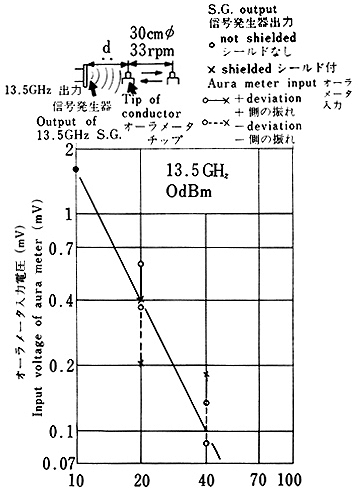 Fig.4 Nearest distance d(cm) 最接近距離 |
Electric lamp as a radiation source. 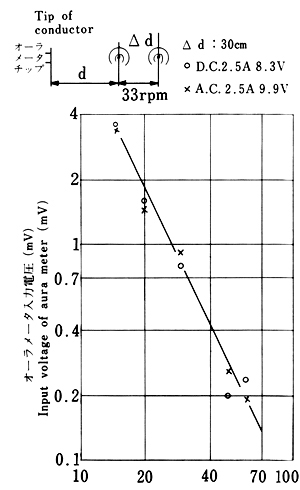 Fig.5 Nearest distance d(cm) 最接近距離 |
第4図は、A - aの実験データ例を示す。
B. 電球光源を放射源とした場合
Aに述べたと同様の現象が観測される。この場合、電源は交流、直流に関係しない。
第5図は、Bの実験データ例を示す。
C. 火花放電が放射源の場合
A-a、bと同様な現象が観測される。 しかし、この場合A-cとは異なり、検出極性は逆転しない。
D. 太陽光、アイソトープが放射源の場合
A-aの場合とは異なり、近づくとき負電荷が減り、離れるとき増える。この場合、シールドによる検出極性の逆転はない。
E. 天体電磁波が放射源の場合
この場合、つぎに述べるような特徴ある現象が観測される。即ち、導体片がオリオン、ペルセウスの方向に動くとき、負電荷が増大し、いて、さそりの方向に動くとき負電荷が減少する。これは東京、大阪、広島、岡山などで した、他の星からの天体電磁波についても、特徴ある現象がそれぞれ検出観測される。
|
1) 毎分10回転 2) オーラメーター入力電圧 1μV:OdB (-)印は極性を示す。 |
1) 10 rpm. 2) lnput voltage of aura meter 1μV:0dB (where(-)shows the voltage polarity) |
3) April 19, 1975. 4) ……:Tip of conductor without electrical shielding. . ……:Tip of conductor with electrical shielding. |
3) 測定、昭和50.4.19. 4) ……:探針シールド なし ……:探針シールド 付 |
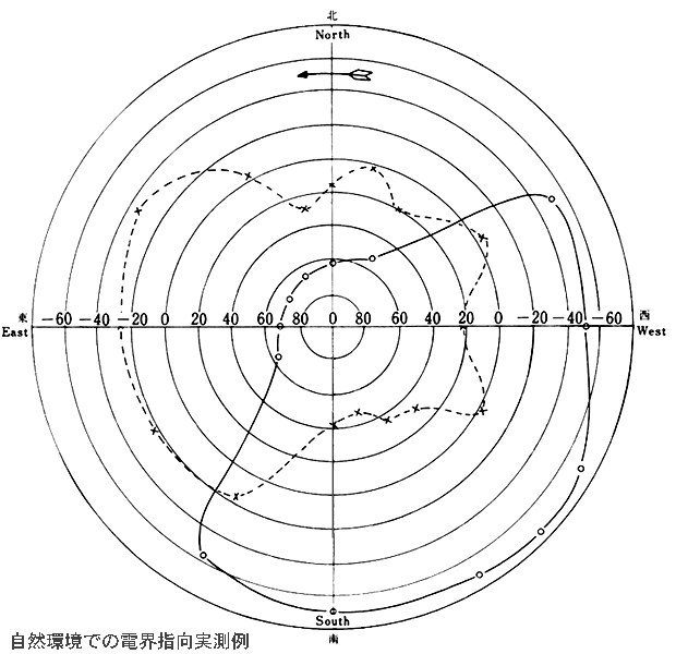
Fig.6 Directional electrical field from the environment
第6図は東京に於ける生活環境で、地上約8メートルの水平面での回転実測例である。プローブの検出用導体片にシールドがない場合には、空気中に潜在する放射電磁波による総合電場に、イオン電場の影響が混入するため指向特性が漠然となる。 しかしシールドをした場合には、イオン電場の影響を軽減除去できるので、主な放射電磁波の到来方向が検出できる。実験によれば、日本最大の300Kw JOAKの放送電波によるエネルギーより逞かに強い電磁波エネルギーが、オリオン、ペルセウス付近、いて、さそり付近、太陽の方向から生活環境に放射していることが観測される。
Fig.7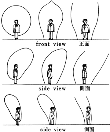
|
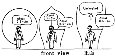 Fig.8 F. 人体の生体エネルギーが放射源の場合 導体片が人体に近づくとき、負電荷が増大し、離れるとき減少する。約4000名の日本人について実測した結果、第7図のような基本的な形状があることがわかった。第8図はその寸法の概略を示す。この寸法は、季節、昼夜、天候、環境空気汚染度によって変化する。 |
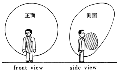 Fig.9 Unusual aura caused by taking food and drink with positive electricity. プラス電気をもつ飲食物によって現れるオーラの異常例 |
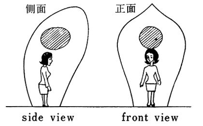 Fig.10 Unusual aura around a person who has anguish of heart. 心に悩みのあるときのオーラの異常例 |
生体エネルギーの輻射は、人間の場合、感情、思考により放射状態に変化を生ずる。頭脳に心配事、疑念があるときには、第10図のように、頭上に放射か弱い部分が動揺している形状で観測される。これは、頭上の皮膚から少し離れた部分から観測される。もし、この放射が弱い部分に動揺がなくて皮膚に接して観測されるときは、寝不足、二日酔などの場合が多かった。
人間は、怒ると第11図の例のように1本または、2本の角状の放射異状部分を生じ数時間持続することが観測された。
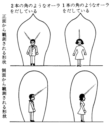 2-horn like aura 1-horn like aura Fig.11 Unusual aura around an angry person. 怒っているときのオーラの異常例 |
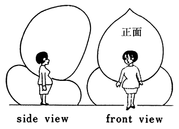 Fig.12 Shape of aura around a pregnant woman. 妊婦の場合は第12 図のように、胎児からの生体エネルギーが別に放射し、その境界面は数センチの検出極性逆転層が観測される。 |
 Fig.13 Unusual aura around a person who has been operated upon for appendicitis. 盲腸の手術をしたことのある方のオーラの異常例 |
第13図は盲腸を手術したことのある人体のオーラ放射の異常例で、衣服に関係なく観測された。
稀には特定の人体について、つぎのような現象が観測される。それは導体片が人体に近づく場合、頭の上とか衿の周囲で負電荷が滅少し、離れるとき増大する。この場合、検出値が一般の平均値より電圧比で100倍以上、電力比で10.000倍以上の異常な強度で検出され、シールドによる検出極性の逆転がない。ニのような人体は、少年、少女に多く観測され、金属製スプーンを頭の上とか跨の付近に持ってくると、工具を使わなくても、地球引力を利用した僅かの反動力でスプーンが変形する現象を起す。
G. 植物の生体エネルギーが、放射源の場合、
a. 導体片がある植物の幹、枝や葉に近づくとき、負電荷が増大し離れるとき減少する。
b. 根がない植物や、枯れた植物の幹、枝や葉の周囲では検出極性が逆転する。
c. 導体片ををシールドした場合には検出極性が逆転する。
d. 幹の方向に直角に、導体片を動かすと幹内部の年輪の粗密に対応するらしく、検出指示に微小な波形の変化を伴う。
H. 放射源を勣かし、導体片を固定した場合、
天体電磁波の場合を除いて、以上に述べたと同様な現象が観察される。
4. あとがき
ここで述べた電場誘導効果による電場分布は、一見、静電場を観測しているようであるが、電磁エネルギー放射場のなかにどうして静電場に似たエネルギー分布が存在するのか、検出極性が互に反対の2種類の電磁エネルギー放射場がどうして存在するのか、シールドによって、検出極性が逆転する場合としない場合があるのはどういうわけか、電磁波エネルギーの性質について、充分な説明ができない問題が存在するのではないかという事実が、以上述べた実験から明白になった。
これは将来に於いて、電磁場に於けるフアラディの法則のように、電磁気学に非常に重大な貢献をもたらし、オーラ現象の謎を解くに役に立つであろう。
このような形式の研究報告は、今日まで取扱われていないし、またこの問題について、数多くの検討がなされなければならないことは明白である。
この実験、研究については、1975年6月30日から7月4日まで、モンテカルロで開催された第2回サイコトロニク ス国際会議で報告した。(参考資料-2)
この研究に関して元電気通信大学教授、関英男工学博士の助言と協力を頂いたことに心から感謝の意を表する。
参考資料
1) Maxime G. Kaufman:(U.S.Naval Research Laboratory) "Force Field Detection of objects in Space", (1966 IEEE lnternationaI Record, Part 10).
2) Hideo Uchida: "Electric Field lnduction Effect and its Apphcation to Flying Saucers," (2nd lnternational Congress on Psychotronic Research, 1975)
Received : January 30, 1976